

Engineering Projects
Selected engineering projects highlighting my approach to solving complex mechanical problems through design, analysis, DFM, prototyping, and hands-on manufacturing.

FSAE Projects
Center Lock Hubs and Nuts
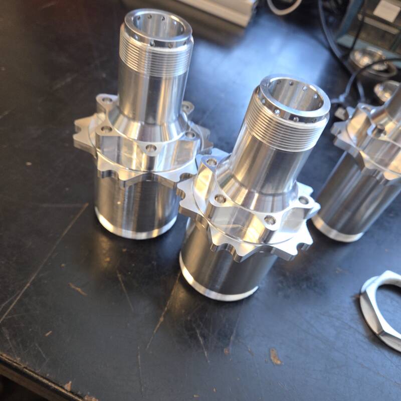
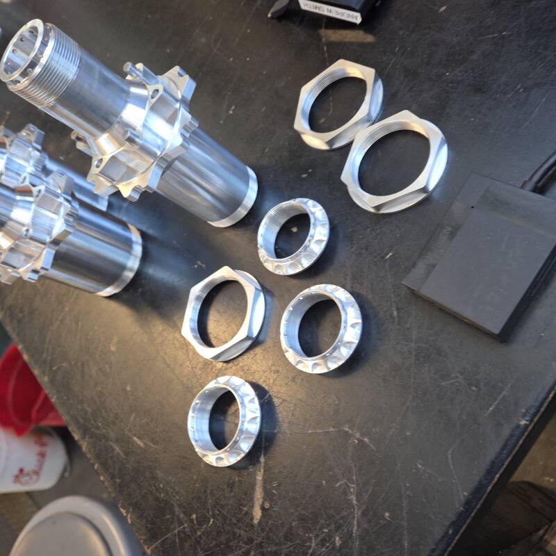

Role: DFM Owner / Manufacturing Lead
Vehicle: VM26 FSAE EV
Skills: DFM, DFA, Tolerancing, CNC Manufacturing
I took engineering ownership of the VM26 front and rear wheel assemblies, leading design-for-manufacturability, tolerancing, design-for-assembly, and CNC manufacturing of the center-lock hubs and nuts.
Key Engineering Considerations
Critical Bearing Fit: The inboard bearing bore was specified with a unilateral diameter tolerance of +0.0003 / −0.0000 in to achieve the required bearing interference fit. This critical feature drove machining strategy, process control, and dimensional inspection of the finished hub.
Center-Lock Retention & Assembly Stack-Up Tolerancing: The center-lock system uses safety wire as a positive retention method. Safety-wire holes in both the hub flange and center-lock nut therefore had to be carefully clocked and positioned so that the assembled components provided a practical safety-wire path despite dimensional and assembly stack-up variation.
Wheel-Center & Shear-Pin Interface: The wheel center has shear pin holes and so does the hub, these shear pins are floating and the wheel center is retained using a tapered center lock nut. This required extremely tight tolerances to maintain accuracy for the shear pin centerline and pattern. This was an extremely tough process since the wheel centers and the center-lock hubs were made in different machines entirely so ensuring the parts met our floating fit spec took very careful planning and precise QC measurements.
Together, these requirements demanded tight functional tolerances, reliable assembly, manufacturability, and repeatable CNC production across the front and rear wheel assemblies.
Fixture Plate and Rotors


Role: DFM Owner / Manufacturing Lead
Vehicle: VM26 FSAE EV
Focus: DFM, Fixture Design, CAM, CNC Manufacturing
I took engineering ownership of the manufacturing development for the VM26 brake rotors, including DFM, machining strategy, fixture design, and dimensional verification. Because the rotors have tight flatness and inner contour requirements, as well as a large number of machined features, the manufacturing process had to be designed around minimizing plate spring back and residual stress distortion from being machined while also being repeatable.
Key Engineering Considerations
Critical Flatness & Rotor Geometry: Maintaining rotor flatness was a primary manufacturing challenge due to the thin geometry and susceptibility of the part to distortion from both clamping forces and material removal. The worry was that since only one side of the stock was being faced, the already warped stock plus any distortion caused by residual stress would cause issues with flatness due to spring-back after it was unbolted from the fixture. The machining sequence, work holding strategy, and cutting parameters therefore had to be developed to minimize induced deformation while maintaining consistent rotor thickness and geometry.
Custom Fixture Design: I designed a dedicated fixture plate to provide repeatable location and support throughout the machining process. The fixture needed to constrain the rotor securely without over-clamping the thin section, while also providing adequate tool access to the braking surface, internal profile, and repeated hole patterns. Developing the fixture required depth clearance for the holes, datum repeatability, and ease of loading between parts. Fixture and part rigidity were also major factors since the inner contour of the rotor is supported by floating titanium rotor bobbins so if the part was not rigid then the inner contour could be inconsistent and the floating fit could be out of spec.
Feature Location & Manufacturing Repeatability: The rotor geometry contains a high number of repeated machined features distributed around the part, making accurate positioning and consistent datum control important. The fixture and CAM strategy were developed together so that critical features remained accurately located relative to the rotor centerline while allowing the same manufacturing process to be repeated across the complete set of rotors.
Aero Package DFM, Mold Design, and Layup


Role: DFM Owner / Manufacturing Lead
Vehicle: VM26 FSAE EV
Focus: Composite DFM, Mold & Fixture Design, CNC Manufacturing, Layup
I took engineering ownership of the manufacturing development for the VM26 aerodynamic package, with responsibility for turning aerodynamic surface geometry into composite components that could be accurately manufactured and assembled. My work included DFM for the undertray, front and rear wing elements, body panels, and sidepods, as well as the design and manufacturing of molds and fixtures used throughout the layup process.
A major part of the work involved determining how complex aerodynamic geometry could be made while maintaining surface accuracy, high volume fraction, and reliable part release. This required thoughtful mold design, tooling access/clearance, draft and release direction, layup accessibility, and the limitations of our CNC equipment and composite layup capabilities.
Key Engineering Considerations
Mold Geometry & Manufacturability:
Complex surfaces had to be converted into male or female molds that could both reproduce the intended geometry and be manufactured using available CNC equipment. Mold geometry was developed around tool accessibility/clearances, tool reach, stock size, surface finish requirements, and a practical part-release directions. Where necessary, molds were segmented to make otherwise inaccessible geometry manufacturable such as when molds were too "deep" for our tooling setup.
Composite Layup Accessibility:
The molds were designed around the physical requirements of the layup process rather than simply reproducing the aerodynamic surface. Particular attention was given to allowing reinforcement plies to conform to tight curvature, providing sufficient layup access, and avoiding geometric features that could create drapability issues, wrinkling, or ply layer defects.
Tooling, Fixturing & Process Repeatability:
Mold and fixture design were developed together with the intended manufacturing sequence so that components could be consistently located, trimmed, bonded, and assembled. Repeatable tooling datums and interfaces were incorporated where possible to reduce alignment variation between independently manufactured composite components.
Create Your Own Website With Webador